28+ am transmitter block diagram
The block diagram of AM. Low Level AM Transmitter Block Diagram There are two signal paths in the transmitter AF and RF.

Fm Transmitter Block Diagram And Explanation Of Each Block Pdf Block Diagram Fm Transmitters Diagram
TRANSMITTER In this block diagram of communication system the upper section is called the transmitting section.

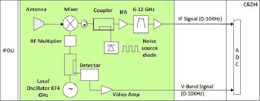
. In a single-sideband transmitter ssb only one of the sidebands the upper or the lower is transmitted while the remaining sideband and the carrier are suppressed. The RF signal is created in the RF. 5 TRANSMITTER The main parts of transmitter are explained as follows.
Final I2S transmit block diagram Test The test will instantiate your i2s_transmit module and an AXI 4 streaming master module to connect to the slave interface on your design. Both pilot monitors change the block diagram of and am transmitter. Illustration by Mark Wickert PhD.
Nalazite se na prodavnicu koja je namenjena. This document contains proprietary information and such information may not be disclosed to others for any. Up to 3 cash back DVOR TRANSMITTER.
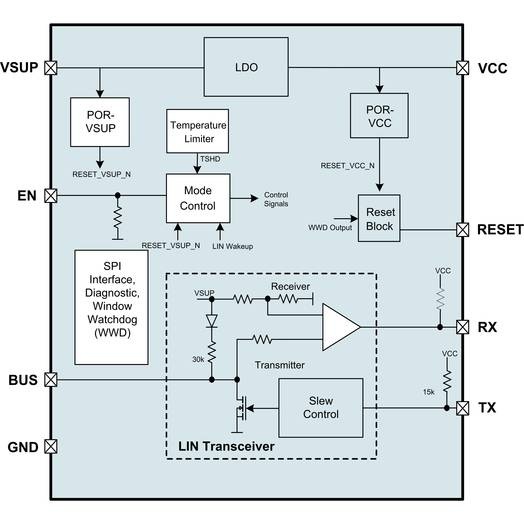
Purpose nor used for. At test point A the. The system block diagram for the transmitter and receiver transceiver is shown here.
Block diagram of television transmitter. Communications equipment is often used. AM transmitter takes the audio signal as an input and delivers amplitude modulated wave to the antenna as an output to be transmitted.
About Press Copyright Contact us Creators Advertise Developers Terms Privacy Policy Safety How YouTube works Test new features Press Copyright Contact us Creators. The basic television Broadcast transmitter block diagram is shown in figure a. The RF signal is created in the RF carrier oscillator.
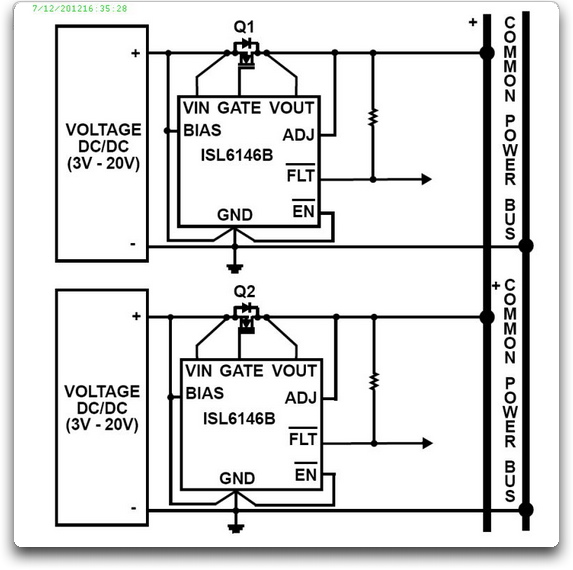
The block diagram can be broadly divided into two separate section viz. A one pair cable is used to power the transmitter and the same cable is. The PLC DCS Analog Input card transmits a standard 24 V DC 20 mA signal to Power the Transmitter.
Complete the diagram. Low Level AM Transmitter Block Diagram There are two signal paths in the transmitter audio frequency AF and radio frequency RF.
Power Systems Design Psd Information To Power Your Designs

Am Transmitter Build Project And Demo Youtube Transmitter Projects Radio

This Simple Am Transmitter Circuit Include Of Many Parts There Is A Transistor Q1 Act As Increase Th Electronics Circuit Basic Electronic Circuits Transmitter

Make Your Own Low Power Am Radio Transmitter Science Project Electronics Basics Science Fair Projects Science Projects

A Low Power Am Transmitter For The Broadcast Band Transmitter Shortwave Radio Radio

Circuit Diagram Circuit Diagram Transmitter Circuit

A Simple Am Transmitter Circuit With Diagram And Schematic This Am Radio Transmitter Can Transmit Transmitter Electronics Circuit Electronic Circuit Projects
Power Systems Design Psd Information To Power Your Designs

Am Transmitters Block Diagram Transmitter Communication

And Final Amplifier It Is Well Known That Poor Transmitter Designs Tend To Modify Freq As You Adjust The Final Stage Wit Fm Transmitters Transmitter Circuit

Mw Transmitter This Oscillator Produces A Continuous Signal In The Medium Wave Band Mw The Signal Strength Transmitter Electronic Circuit Projects Ham Radio

Lm386 Crystal Oscillator Am Transmitter Electronic Schematics Am Radio Stations Fm Transmitters

Cheap And Chirpy 1 Transistor Cw Transmitter 2 Watt 12v Electronic Schematics Qrp Transmitter
Fig 2 Schematic Diagram Of Dsb Transmitter For 10m Transmitter Radio Radio Antenna

Am Verici Devresi Am Transmitter Uydudoktoru Transmitter Electronic Circuit Projects Electronic Schematics
Icecube

Ecl85 Am Transmitter Amatorradio